Modulbauworkshop in Athen
English text by Nick Fotis
Nick Fotis und ein paar Freunde bauen in Athen Module.
Diesen Bericht hab ich mit seiner Erlaubnis hier eingestellt, da vieles davon auch
beim Zusammenbau anderer Modularten hilfreich sein kann.
Dies bezieht sich insbesondere auf die Verwendung von IKEA-Beinen.
Danke an Nick für den Bericht
Hello there,
we had a small FREMO module workshop in Athens in November 2007, it may be
interesting to other modelrailroaders.
I guess our technique may be interesting to them.
1. Basic material:
Side panels (we used mountain profile based on FREMO design, 50cm
wide), plus two 100cm long and 13.5 cm tall wood boards, all made by plywood.
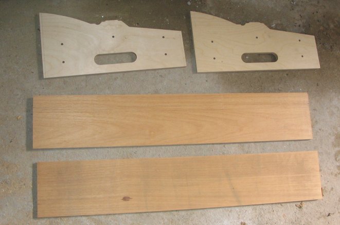
2. The first panel is taller than necessary for the foreground side,
so we decided to cut some extraneous wood (we decided on a limit of 12cm from base bottom).
Used a power saw and we did not cut it in a straight line, for a more 'natural' result.
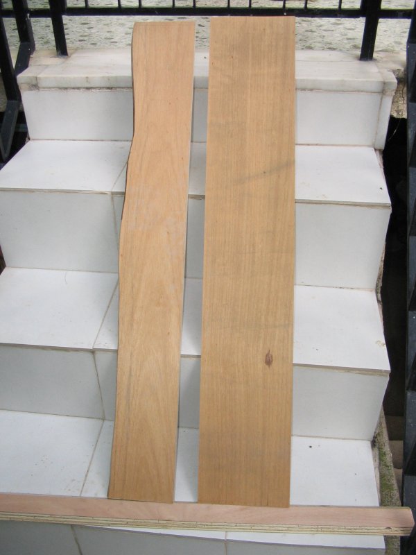
If you watch the bottom view of the photo, I had ready a long board
that will serve as a track base (after we add some cork too). Note
that I had asked for this board to be cut in a 'prismatic' profile
(more suitable for adding ballast later).
Base had width 6cm and height 1.2cm.
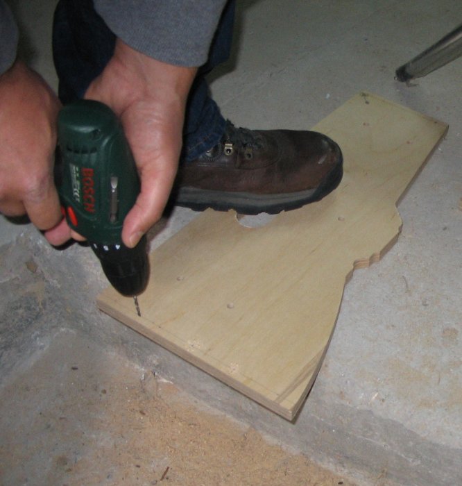
3. We had to do some guiding holes at the side profiles, to make
easier screwing these to the boards.
We spaced the 2mm holes every 5cm, starting at 2cm from the bottom,
following a line 7mm away from the profile edge (the boards have 15mm
thickness). The wood screws we used are 4cm long with 3.5mm diameter.
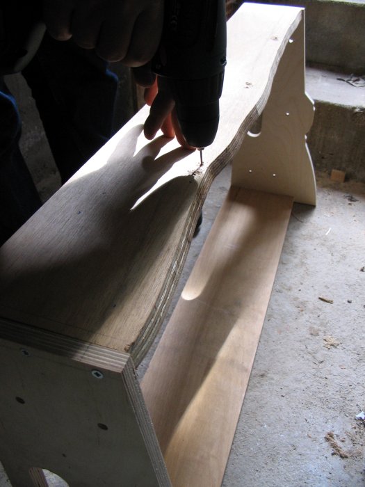
4. After we screwed the four sides, we had to do guiding holes for the
horizontal members that would add strength to the whole box. We cut
the small boards tailor-made for the occassion, from available remains
from other plywood boards.
Since we are going to use blue extruded foam (Dow is the European
trademark), with 3cm thickness in two layers (in order to use most of
the big plastic piece inside), we made the holes at 11cm from the base bottom.
If you use 5cm (= 2 inches) thick foam boards, move the holes down
four more centimeters (this limit also has to do with the 12cm limit in the 1st step)
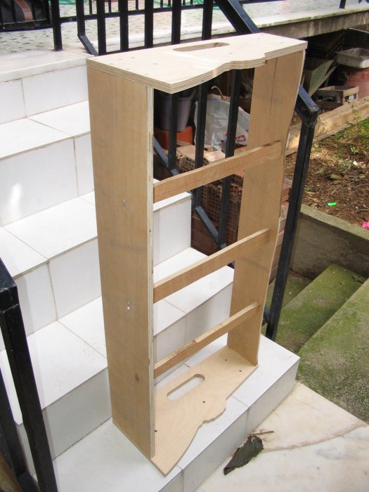
(note: we concluded that it would be a good idea to have the outermost
horizontal members nearer the edge, so the foam board sits better at the edges.
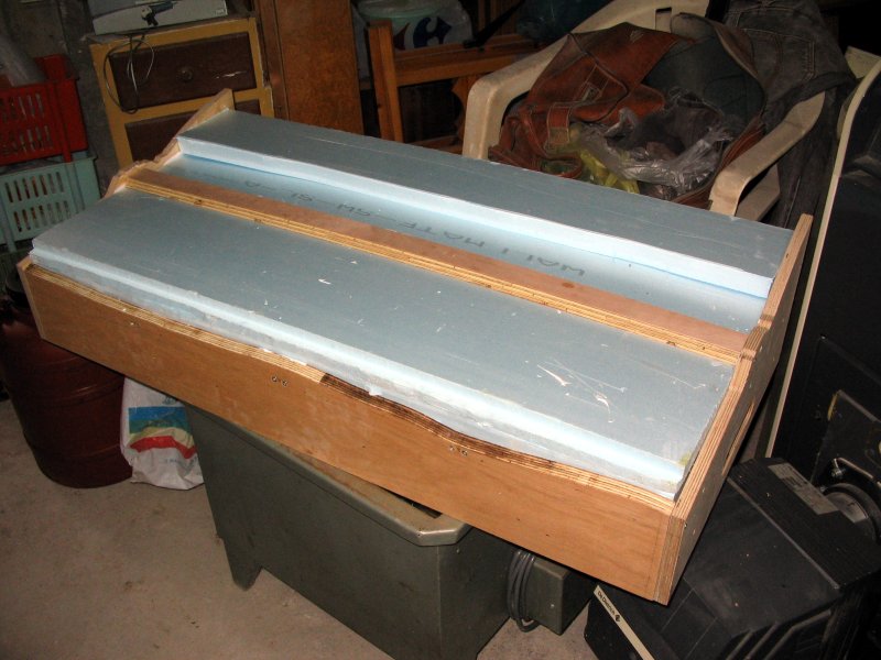
5. After a hour of relaxed work, the basic box poses for us
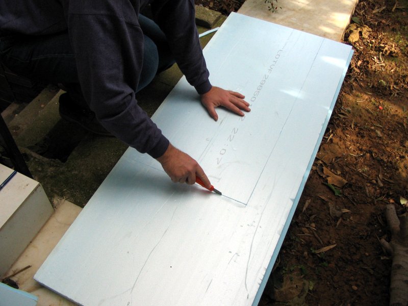
6. Now, we have to cut the foam board in order to fit the pieces
inside the box. We trace a line from inside the box, then use a hobby
blade (pull it repeatedly along the traced line for cutting it).
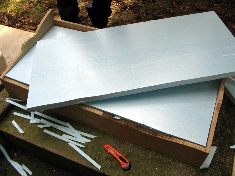
7. We cut two pieces of foam board, and test fitted it to the box (we
may have to 'shave' some of the foam, in order to get a better fit).
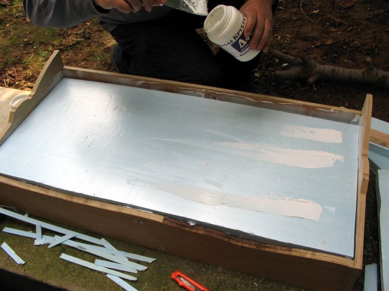
8. We are applying matt white glue (the same that is used for
ballasting too), first at the horizontal members, then at the
periphery of the box (in order to secure the extruded foam better).
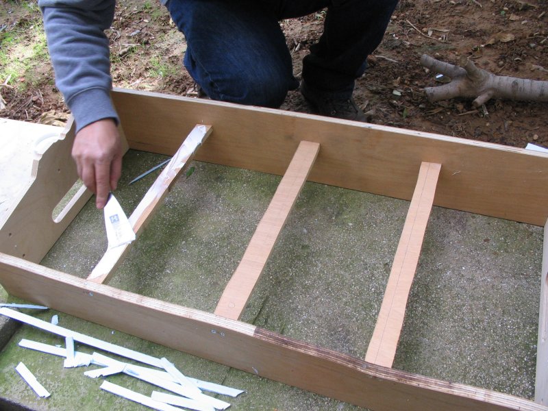
9. As you may have noticed in the previous photo, we use a spatula for
applying the white glue. Then, we add another dose of glue on top of
the first board, in order to glue the second one.
Here it is the most enjoyable part of the construction, since we can
be as messy as we want :-)
10. The base box is ready, after we added the track base (screwed at
the
side profiles, also glued at the foam board). Total time: a very relaxed 3.5 hours.
[ intermission for a nice family lunch... ]
Now, we have to add the module legs.
We decided to try with the IKEA legs hinted by German module builders
(series IVAR, side panels, height 124cm and width 50cm).
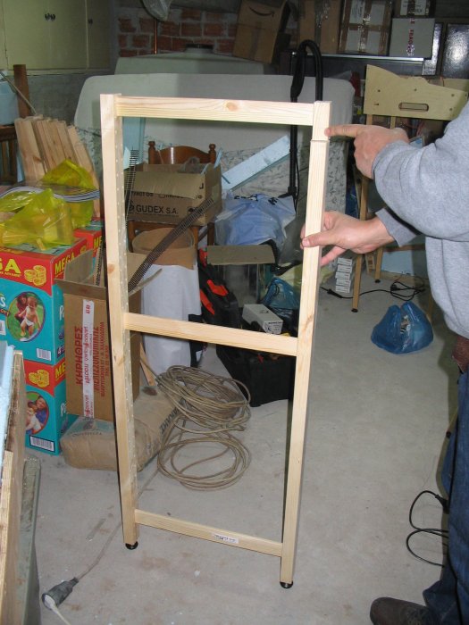
11. Here we see the IKEA legs, where we have added screws at the
bottom for adjusting the height. Very big, and very sturdy (solid
wood, 3*4cm profile, plus horizontal braces from the same material).
Cost: 10 Euros per piece (gives two legs), added two adjusting bases (1.11 Euros per base)
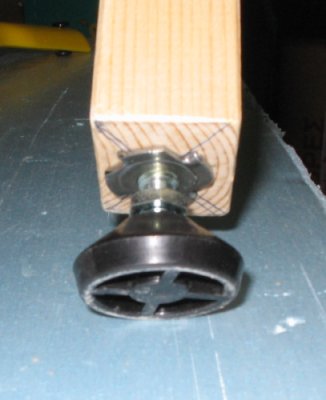
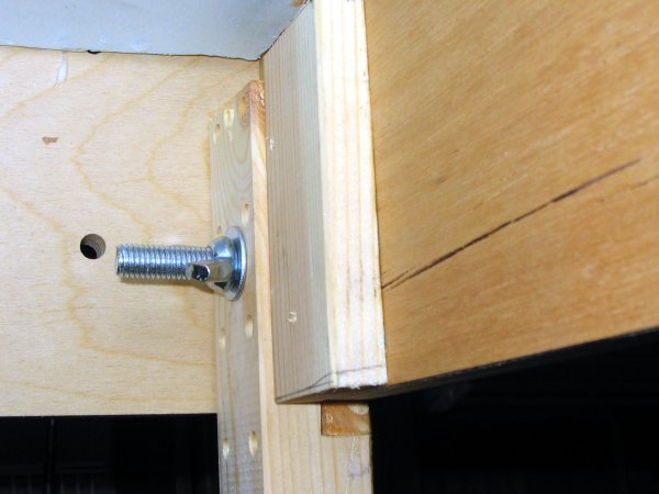
12. Here is a close-up to the adjusting screw (one piece is hammered into
the wooden leg, and the second piece, well, screws into it). The diameter is 10mm.
13. Because the module has the same width with the leg pair (50cm), we had
to 'eat' a piece from the legs (after shortening these to the necessary height too).
I used my power saw, but it was rather hard (their wood is very hard when trying to cut it along the leg).
With this trick it was possible to enter the pair of legs into the module box in a move.
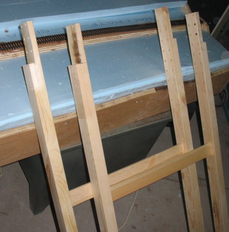
14. Because that particular module is rectangular, I could simplify
the mounting construction even more.
I added the piece I cut in the previous step, so as to limit the
movement of the leg even more (screwed this piece permanently). Each
leg is screwed with one big, honking screw held stable with a
butterfly nut (not sure about terminology here).
The screw had diameter 10mm and length 6cm.
The result seems very light and stable, with very fast set-up time.
In the interior angle shot I added, you see the bottom of the foam
board above the screwed leg, which is limited at the angle.
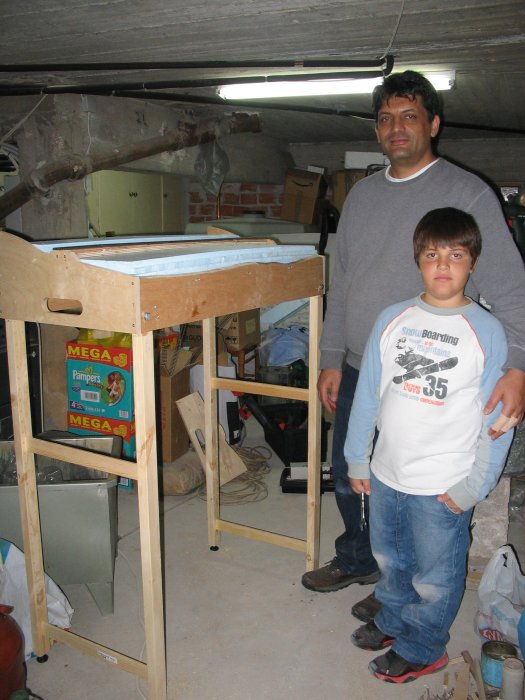
15. Our new modellers with their first module. Let's wish them lots of trips!
Next step: to find a simple and easy way for soldering the Marklin
K-track (code 2205), which has proved really hard to solder (using
rail joiners seems necessary for making electrical connection).
We wish to make a 'universal' module, which will be able to run DC/DCC
and AC/AC Digital (after doing lots of weathering, ballasting, etc.,
we hope to hide these center studs well enough).
After these problems are solved, the next stage is 'landscape' and 'scenery'.
hint: search on youtube.com with the words: extruded foam ...
Cheers,
Nick Fotis

Hier geht es zurück zur Index-Seite